
Imagine… You’ve drawn and redrawn dozens of designs, consulted countless experts about your plans, worked with officials to secure approvals. And now, at last, the first day of construction has dawned. How do you feel? A mix of relief, excitement and also some terror. This has got to work…
That day and these feelings came for the designers, engineers, and constructors of the Forth Bridge on 6th June, 1883. If you’ve followed the story of the bridge through the preceding blogs, you’ll understand that behind that day lies a long history of crossing the Firth of Forth: ferries for people, animals, carts; ferries that carried trains; plans for bridges; plans for tunnels. Every major project had stalled or failed. And June 1883 is only 3 years, 5 months, 1 week and 1 day since the bridge over the nearby River Tay collapsed in a storm with the loss of 75 lives. Now they are daring to bridge the Forth?
Benjamin Baker (designer), John Fowler (consulting engineer), and William Arrol (building contractor) must have been nervous. Yet, they’d already poured their skills and hearts into this project, and their will for it to succeed was as strong as the steel with which the bridge would be built. So the work began.
Because the Forth Bridge became recognized around the world as an engineering marvel, there are mountains of technical information about its design and construction. I’ll try to keep the story moving, though mostly the remarkable engineering work at this bridge is the story. But, if the detail is too much, jump ahead a little to find what interests you.
Foundations
I was pastor of a new church in Livingston, West Lothian. Initially we met in a school but when numbers grew money was raised, a site bought, and foundations were laid for our own church building. But there was a complication for those foundations. Years before, our site had been a dumping ground for loose soil. So our contractor’s team had to dig through all that landfill until they reached firm ground, a solid base. Then, in the trench they’d formed, they poured concrete which, when set, became the foundation on which our building would rest.
In principle, that’s what they did for the Forth Bridge. But its foundations would be under water, and you can’t pour concrete into a tidal river.
So what do you do? You use caissons.
Imagine an open-ended metal cylinder. It could be a tin can without its top and bottom. Now, scale up that can to immense size, something like an old-style gasometer (UK) or a giant water tank (USA). Then picture that sunk into water, and eventually filled with concrete, and you begin to understand what holds up the Forth Bridge.
Each caisson for the Forth Bridge was 70 feet (21.3 metres) in diameter and between 50 and 90 feet (15.2/27.4 metres) high. When empty, each weighed around 500 tons. When filled with concrete they would weigh up to 20,000 tons. They were constructed on shore from wrought-iron, towed out and sunk exactly where a pier was needed.
But you couldn’t just sink a caisson and hope for the best. It had to sit solidly in precisely the right place and at precisely the right depth, with no movement whatsoever. The base of each caisson was pre-shaped for its location, but more work was needed for a perfect fit. That required men with explosives, shovels, pick axes and sledgehammers to blast and break rock so the caisson sat perfectly on the boulder clay and rock beneath the river bed.
The Firth of Forth is tidal, and the changing depth of the river created challenges for excavations inside caissons. You can’t work down a caisson with water pouring in at high tide. Some caissons could be protected by a cofferdam –a temporary circular barrier to hold back water. Then what’s enclosed could be pumped out and work done inside. But others – those near South Queensferry in particular – were under water at high tide and low tide. How could men work at the bases of these caissons?
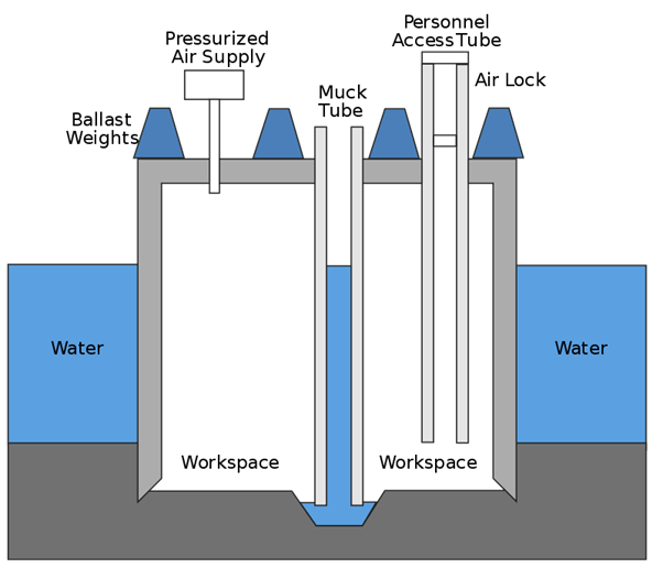
Schematic cross section of a pressurized caisson
The answer was the ‘pneumatic method’. A pneumatic caisson is sealed at the top, then filled (or partially filled) with compressed air. That creates a protected space within which diggers can work. The illustration and line drawing help explain how it was done. An airlock gave workmen entry to one or two shafts down to the work area, and the mud and rock they excavated was lifted to the surface via another shaft, a ‘muck tube’.
The pressurised air flow had to be controlled precisely: a) so that the workers had an adequate supply of fresh air; b) to hold back any significant inflow of water or mud beneath the edges of the caisson.
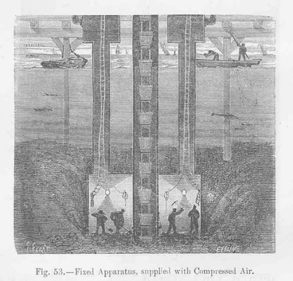
Line drawing of work at base of pressurised caisson
This was dangerous work. A failure with the compressed air would mean the workmen drown. And compressed air risked serious health problems when returning to the surface.
What they called caisson disease is what we now call decompression sickness (DCS) or the bends. Wikipedia describes it as:
‘a medical condition caused by dissolved gases emerging from solution as bubbles inside the body tissues during decompression. DCS most commonly occurs during or soon after a decompression ascent from underwater diving…’[1]
The workers at the bottom of a caisson were breathing air in high ambient pressure conditions and then surfacing to the lower pressure outside the caisson. Unless the pressure was reduced slowly the result would be, at least, severe joint or skeletal pain and very possibly death.
Only one death from caisson disease was recorded at the Forth, but just a few years earlier, during the construction of the Eads Bridge across the Mississippi River, 15 caisson workers died, two were permanently disabled and 77 severely afflicted because of the disease.[2]
Before moving on, imagine the conditions for these caisson workers:
- they climbed down ladders into a sealed space under the River Forth;
- they had no more than seven feet (2.1 metres) of headroom;
- their whole shift was spent hacking at clay and rock with heavy tools, then lifting the muck into ‘baskets’ to be pulled to the surface;
- if there was an emergency with the compressed air or flooding, they’d have to exit, but to escape to the surface quickly would likely kill them.
Of all miserable and risky jobs, that must rank near the top of the list.
The only humorous thing I’ve found about the pneumatic caissons comes from Murray (in his book The Forth Railway Bridge) who describes a visitor descending into the underwater chamber to see the work. Impressed, he brought out his flask, and offered the men (mostly Italians) a ‘wee dram’ of his whisky. No doubt they appreciated it. And there’s no doubt the visitor didn’t realise his flask was now full of compressed air until, that is, he climbed out of the airlock at the surface and his flask exploded.
It took three years for the caissons to be finished. They’d been filled with 21,000 tons of best Portland cement and surrounded by 740,000 cubic feet of best Aberdeen granite. But the piers are built. Now it’s 1886 and at last work on the bridge itself can start.
Superstructure
This will be a giant of a bridge:
- Its overall length will be more than 1.5 miles (2467 metres)
- It’ll rise almost 450 feet (137 metres) above its foundations, 361 feet (110 metres) above high tide
- It’ll be made of steel weighing 53,000 tonnes (52,163 imp tons; 58,422 N Am tons)
- The riggers will use 6.5 million rivets (that’s the oft-quoted number, but several experts think the real number of rivets was 7 or even 9 million)
Whole villages of huts had already been created on both shores, and on Inchgarvie island. Some of these accommodated workers, though many of the ‘briggers’ had to be transported to the site each day. There were other huts for joiners and carpenters, offices, sheds to store materials, and larger ones for the assembly of steel plates. At the busiest time for construction, the village and building site at South Queensferry covered 60 acres.
The local site was not equipped to manufacture the largest bridge parts. They were made of the best steel in foundries in Glasgow, Motherwell and Swansea. Large plates and girders were cut at South Queensferry, where a huge loft was set up so templates and patterns for those plates could be drawn ‘life-sized’ on a blackened floor.
The bridge would be of enormous weight, but not as much as it might have been. To lighten the load the major compression members were designed as tubes, using steel 1¼ inches (3.2 cm) thick and 12 feet (3.6 metres) in diameter. (As a child I remember being told that workers walked up and down inside those tubes. I wished I could do that!) The bridge designer, Benjamin Baker, said that the weight those tubes would carry (i.e., the bridge’s own weight, plus the weight of trains and wind pressure) would be the same as a transatlantic liner filled with cargo. The tubes would be held together with a web of steel girders. Expansion joints allowed for up to 18 inches (46 cm) of movement caused by temperature variations. (The photograph of the base resting on its piers provides a good close-up of the compression tubes and girders.)
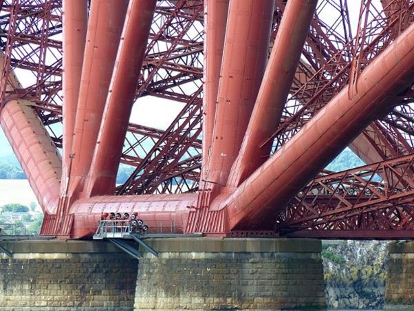
Close up photo of bridge resting on its piers
The first bridge section built were the towers. They had to be first because this was a cantilever bridge. Let me explain.
Here’s one description of a cantilever design: ‘This type uses a pillar anchored vertically into the ground to support a horizontal deck extending out from one or both sides across the span.’[3] In other words, a strong vertical piece is the sole support for an attached horizontal piece.
The simplest example of cantilever design involves a diving board. Usually there’s an upright tower, from which a diving platform or board projects out. All the weight is carried back down to the ground by the tower. Now – in a flight of imagination – picture two identical diving boards facing each other, with their diving platforms meeting in mid air. What do you have now? You have a bridge. You could walk across from one tower to the other, each half of the platform you’re crossing fixed to its tower.
Small section of original bridge design drawing
That’s almost exactly the design of the Forth Bridge. I’ve put part of an original design drawing of the bridge alongside – it shows just two towers (the rectangular vertical sections supported by X-shaped girders), each tower consisting of two pairs of pillars,[4] with upper arms stretching sideways from the top and tilting downwards. Each arm reaches track height where it supports a small ‘suspended span’ in the middle. (Further weight is taken by the lower, curved compression members.)
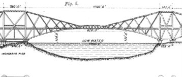
The Forth Bridge is actually a twin cantilever design. That sounds complicated but isn’t. Imagine standing with each of your arms stretched sideways away from your body while you hold a bag of flour in each hand. You are now a twin cantilever because you reach out in two directions. Then imagine another person stands in exactly the same posture next to you, your hands touching only to share the weight of the bag of flour you both now hold. Finally let’s add a third person, again arms outstretched and sharing the weight of the flour bag held by his neighbour. You have created the Forth Bridge. What three people can do holding bags of flour is parallel to what’s done with pillars and cantilever arms in the Forth Bridge. You can see that shape by looking now at the full-length design drawing (just below). Each tower has twin vertical pillars because their cantilever arms reach out sideways in opposite directions. Instead of a bag of flour, they each support a small span of girders where their arms almost touch. At the far right and far left the arms rest on pillars that carry the ends of the rail track to the shore.
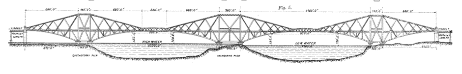
Full length version of original design drawing
Of course, by major steelwork those cantilever arms (working with lower compression tubes) bear most of the weight of the whole bridge. They’re linked to the track where trains cross and to other parts of the bridge. The suspended spans between them are far lighter for those cantilever arms than bags of flour are for us.
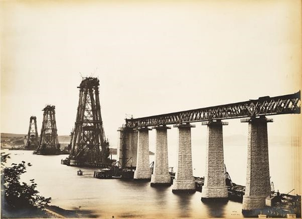
View from S Queensferry, 1887 – almost the only work on the bridge at this stage is the construction of the towers

View of bridge in 1888 – the twin cantilevers arms from each tower reach out, with support from a lattice of trusses
If – hopefully – you’ve followed some of my amateur explanation, you’ll understand that the weight in a cantilever design depends on the vertical towers because they’re the only parts which rest on the foundations. Nothing else about the Forth Bridge could be built until they were in place. Even then the cantilever arms had to be added at an equal rate to both sides of the towers to ensure balance. So – as further photos show – the bridge gradually expanded outwards from each of the three towers until eventually they were within ‘touching distance’ of each other, and could be finally linked by those short spans.
One more detail. The Forth Bridge is technically a cantilever-truss design. The construction expert I quoted earlier writes: ‘Cantilever bridges are often supported with trusses. A bridge truss takes the load off the deck and transfers it to the supporting piers and abutments, helping the cantilevers withstand tension in the upper supports and compression in the lower ones.’[5] I believe he’s saying the trusses within the Forth Bridge push the weight of trains onto the larger structural members.
Accidents
Many died during construction of the bridge. In an earlier blog, I said the number was more than those drowned in the Tay Bridge disaster, which was 75. Official figures for deaths while building the Forth Bridge give a number of 73. So I was wrong – maybe. The hesitation is because sometimes men killed working on the approaches to the bridge were not counted, nor those who died later from injuries sustained while working on the bridge. Perhaps some were never counted. Of course there were also those who only nearly died, such as the eight men who fell from the bridge while working and were rescued from drowning by boats stationed in the water below. As of 2009, the official figures say this: ‘Of the 73 recorded deaths, 38 were as a result of falling, 9 of being crushed, 9 drowned, 8 struck by a falling object, 3 died in a fire in a bothy, 1 of caisson disease, and the cause of five deaths is unknown.’[6]
I said in an earlier blog that there was a surprising explanation for so many accidents. That was drunkenness. Any worker found drunk was sent off the site immediately to sober up. Otherwise he risked his own life and the lives of others. Murray’s book records that Arrol (the main contractor) considered the drinking so bad he instructed that more foreigners should be employed as they didn’t drink as much as the Scots! But drunkenness wasn’t the only cause of accidents. Apparently some of the younger briggers were foolhardy enough to ignore safety ropes and jump from girder to girder while hundreds of feet up. Not all were successful.
Most likely the high accident and death toll was simply because it was dangerous to build a bridge so high and so wide through all seasons across a wide estuary exposed to the frequently severe North Sea weather.
Finished, tested and opened
Work on the bridge was 24/7, stopping only when the strongest of winds made it impossible to be on the bridge safely. Night-time work required lighting. Gas was too expensive; oil lamps were dangerous. So they used electricity, very new at the time.[7] Occasionally it failed, leaving workers in exposed locations in darkness.
Finally the work neared its finish. The last connections had to be made when the steel was in precisely the right position, neither expanded because of a high temperature nor contracted because of a low temperature. Temporary bolts were inserted initially, and then they had to wait several days more for a good temperature. On the morning of 14th November, 1889, everything was exactly right, and the final connection made. Thirty six temporary bolts still had to be removed, but before that could be done the temperature dropped, the bolts sheared with a sound like a cannon firing, and a small shake went through the bridge. But, as the bridge designer said later, the only consequence was that work removing 36 bolts was saved.
The official load testing of the bridge took place in late January, 1890. The test involved two trains, but each ‘train’ actually consisted of three locomotives towing 50 wagons loaded with coal. The total weight was 1880 tons, more than twice the design load for the bridge. They moved across the bridge, stopping several times for deflection measurements to be made. Nothing adverse was found. The bridge passed its test! The first official crossing took place the next month involving railway company dignitaries.
The official opening was on 4th March, 1890. One of the guests on the day was Gustave Eiffel, the civil engineer responsible for the Eiffel Tower which had opened to the Paris public only the previous year. But it was the Duke of Rothesay, later to become King Edward VII, who hammered home the last rivet, this one gold plated. Oddly, though there are several line drawings of the opening ceremony, I believe there are virtually no photographs.
Facts from then until now
At the time of opening, the Forth Bridge had the longest single cantilever bridge span in the world. In 1919 the Quebec Bridge in Canada exceeded it, but the Forth Bridge continues to be in second place.
The total construction cost was £3 million, a huge sum in the 1880s but unsurprising for a bridge of such strength across a wide estuary. Cost is a major reason why few other bridges like it have been built.
Probably no-one has ever known the overall number employed to build the bridge. That would have to include all the staff in design, engineering and construction offices, in foundries in other cities, those who worked on approach piers and railways lines to the bridge, building sheds for storage, preparing meals for workers, and so on and on. Many briggers stayed for only a few weeks before moving on, in total a very large number. The only figure commonly stated is that 4,600 men were employed at the height of construction.
It is a myth that painting the Forth Bridge is continuous. For generations it was said that when the painters finished at one end they immediately restarted at the other end. That has never been true.
Right now the Forth Bridge requires virtually no painting. A major refurbishment project began in 2001. For ten years sections were screened off to allow sandblasting, minor repairs to the steel, and then a special coating applied of virtually impermeable paint (tinted red). No further work is expected for 20 to 25 years.
As a child I was told people threw pennies out of train windows while crossing the Forth Bridge. It was supposed to bring good luck. It was certainly not good luck for those sailing underneath the bridge who could have been killed by any object thrown from above.
Another thing I learned as a child is that the Luftwaffe tried to bomb the bridge during World War II. This is not true. What is true is that, on 16 October, 1939, 12 German bombers tried to bomb ships moored in the Forth, near to the Rosyth Naval Dockyard and thus also close to the Forth Bridge. Ships were damaged and 16 sailors lost their lives. Two enemy planes were brought down by Spitfires. It was the first air raid over Britain during the war, but the bridge was never the target.
In July 2015 the Forth Bridge was made a UNESCO World Heritage Site. It’s the sixth World Heritage Site in Scotland, and now has the same status as the Taj Mahal and the Great Wall of China. Since 1973 the Forth Bridge has also been a Category A listed building.
Currently 190–200 trains per day cross the Forth Bridge, carrying about 3 million passengers each year.
The bridge has been used in films, notably The 39 Steps in both the 1935 and 1959 versions (though it is not mentioned in John Buchan’s book). It has also been used to market soft drinks, anti-corrosive paint, women’s fashions, oatcakes and it has undoubtedly sold tens of millions of postcards. It’s often been the backdrop for any product from Scotland. Last Christmas my son and daughter-in-law, who live in Edinburgh, sent me a card to which was attached a Forth Bridge badge. Great choice.
Today three bridges cross the estuary of the Forth. Alongside the Forth (rail) Bridge stands the Forth Road Bridge, a suspension bridge, which was opened in 1964. Next in line upstream is the Queensferry Crossing, another road bridge, opened in 2017. The Crossing is the longest three-tower, cable-stayed bridge in the world. Each bridge was built in a different century.[8]
Final thought
I believe nothing made with human hands beats what God has made, such as a dramatic sunset, an awesome mountain range, or the intricate design of a snowflake.
But, even so, we must not be blind to the amazing things that amazing people have made. The Bible says ‘God created mankind in his own image … both male and female’ (Genesis 1:27). That doesn’t mean we look like God but does mean at least some of God’s attributes are found in us. Those include creativity, precision, a sense of what is literally wonder-full.
The Forth Bridge has always filled me with wonder, and the more I’ve looked into its design and engineering the more I’m amazed by the creativity and carefulness of those who imagined and those who built that bridge. I’d be impressed if they’d done it with all the toys of modern technology; they did it without even a calculator.
Not everything we make is good, but many things are. Let’s be grateful for the gifts, the learning, the hard work that people have put in to make these things special.
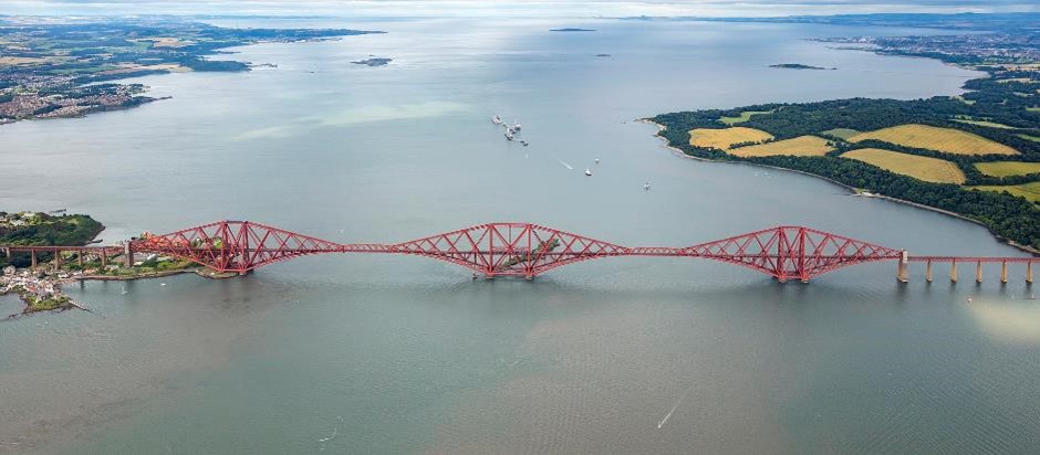
A magnificent 2016 photo of the Forth Bridge, looking downstream (east) towards the North Sea. The built-up area in the upper right is a small part of Edinburgh.
This three-part story of the Forth Bridge is over. First, thank you for your patience, Each part has been at least 50% longer than most blogs (this one even more than that – sorry!). Second, I’m far from being at my best with technical things, so if I’ve got details wrong, please forgive. Third, more normal blogs will be written from now on – in other words, ‘normal service will be resumed as soon as possible’.
——————————
[1] https://en.wikipedia.org/wiki/Decompression_sickness
[2] https://en.wikipedia.org/wiki/Eads_Bridge
[3] https://www.bigrentz.com/blog/types-of-bridges
[4] Because this illustration (and the next) are side profiles, they show only the pillars on the near side of the bridge. Each has a corresponding pillar on the far side, what will be eventually the other side of the railway track. That’ll be more obvious in later photographs.
[5] https://www.bigrentz.com/blog/types-of-bridges
[6] https://en.wikipedia.org/wiki/Forth_Bridge#Accidents_and_deaths
[7] The first time any street in the world was lit by electricity was in 1878 (in Newcastle), only eight years before superstructure work on the bridge began.
[8] I recommend this site for beautiful photos of the three bridges over the Forth: https://www.scotland.org/about-scotland/scotlands-stories/the-bridges
And there is an excellent short video (approx. 7½ minutes) showing construction and features of the three bridges over the River Forth: https://www.youtube.com/watch?v=tgeFKVX2C-o
